
Payment Systems | Vendnet
Quickly and easily find the Parts and Service Manuals, and Installation Guides for your Payment Systems including coin mechanisms, bill validators, and cashless credit card readers. Current payment systems are still being produced, and therefore are supported by Vendnet for parts and service. Current payment systems are also available to purchase if you need a new payment system.
Discontinued payment systems are no longer being produced. Therefore, these payment systems are unable to be purchased new, but many of the Discontinued payment systems are still supported by Vendnet for parts and service.
Vendnet supports discontinued payment systems for a period of time that varies by payment system after the payment system is discontinued. On a case-by-case basis, we may have remaining stock of select parts for payment systmes that are discontinued AND no longer supported.
If your payment system is no longer supported or you do not see your payment system listed on this page, please reach out to us and we will do our best to assist you.
 |
 |
|
|
Model: NBM-3000 Series |
Model: MCM5 Series |
|
 |
 |
 |
|
Model: Greenlite ePort Engage Devices |
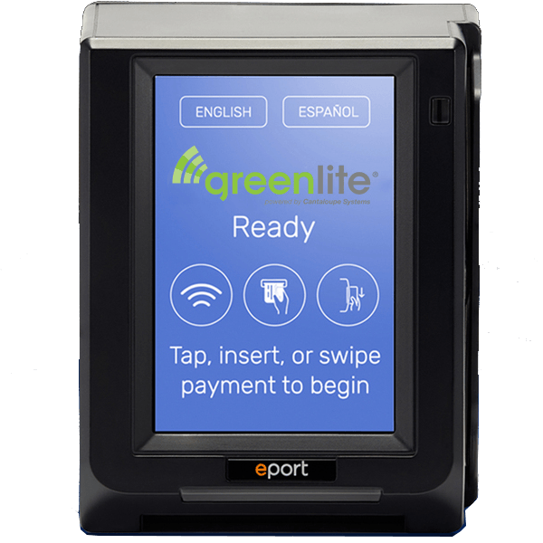
Model: Greenlite ePort Devices |
Model: Greenlite Pico Devices |
 |
 |
|
|
Model: CCM5G Series |
Model: Greenlite Cantaloupe Seed Devices |